Protocols in the Layer 2:
- Wi-Fi (IEEE 802.3)
- Ethernet (IEEE 802.11)
- Token Ring (IEEE 802.5)
- WiMAX (IEEE 802.16)
- High Level Data Link Control (HLDLC)
Sub Layers:
Data link layer is divided into 2 sublayers:
LLC:
- stands for Logical Link Layer
- is responsible for the framing && Mux/Demux, reliability, flow control.
MAC:
- stands for Medium Access Control
- is responsible for the channel access, addressing, error detection + correction.
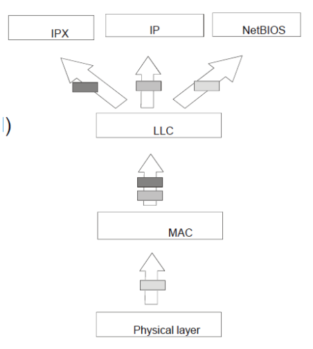
Layer 2 is mostly implemented in the hardware, more precisely the NIC (network interface card) which consist of a controller and a physical transmission.
A small part is implemented in the software, like:
- Controller management
- Frame relay between the machine and the card
Framing:
Framing is the way to write and decompose the frames.
Usually, the PDUs have a limited data size, MTU. In computer networking, the maximum transmission unit (MTU) is the size of the largest protocol data unit “Protocol data unit”)(PDU) that can be communicated in a single network layer transaction. The MTU relates to, but is not identical to the maximum frame size that can be transported on the data link layer.
Larger MTU is associated with reduced overhead. Smaller MTU values can reduce network delay.
Error checks:
*Encoder: process that computes the parity bit based on the information and form combination of information and parity for transmission
we have two types of errors:
- a frame has a/many false bit
- a frame was loss in the transmission, and the receiver is unaware of this frame
The first type of error can be detected by using:
- Parity code
- Checksum
- CRC (Cyclic Redundancy Check)
The second type of error can only be detected by the transmitter.
FEC:
- stands for forward error correction
- it adds redundancy during the transmission
- Useful for long distance communication, like radio messages (not in LANs).
ARQ:
- Stands for Automatic Repeat Request
- ACK is when the destination has received the correct data (acknowledgment)
- NACK is when the destination hasn’t received the correct data, then the sender retransmit the data. (no acknowledgment)
so we have:
Digital message (sent)
        |
        v
FEC encoder (data link layer)
        |
        v
Modulator (modulate the message and transmit over the channel)
		|
		v
	  Noise
		|
		v
Demodulator (produce estimated channel bits)
		|
		v
FEC decoder (estimated channel bits are decoded to provide the decoded message)
		|
		v
Digital message (received)
**Types of modulation:
- QAM (Quadrature Amplitude Modulation)
- PM (Phase modulation)
- AM (Analog modulation)
- FM (Frequency modulation)
modulation is the process of converting Digital signals to analog, by changing the frequency / phase / amplitude.
Error detection with block codes:
There are many types of error checks:
- Hamming
- Check Sum
- Cyclic Redundancy check(CRC)
A code with length n and have information bits with length k will contain n-k parity bits.
The nb of code words in (n, k) block code =
block code is linear if (a, b, c are block codes)
Hamming weight: is defined as the nb of 1’s in the block.
ex: binary block
Hamming distant: is between two binary blocks which is the nb of places in which they differ.
In order to guarantee that the error can be detected, the nb of error hits must be <
The max weight error that can be detected is , a single parity check code has min hamming distance of 2 we can only detect a single bit error in the received binary block
Hamming codes: Several family of the hamming code with several block length.
[n = block code length, m = nb of parity bits]
.
Link access protocol:
- The access method depends on the topology of the connection between two adjacent node
Network Topology: - The graph configuration of a network, where devices are represented by nodes and links by arcs.

central node: the node that is connected directly to all the other nodes. also known as master-slave (example: star / extended star)
Logical vs Physical topologies:
- Physical is the physical form of the network.
- Logical indicates how information flows through the network.
Point-to-Point topology:
- A node is logically connected to only one other node.
- For a layer 2 (MAC) frame, this is simple because no addressing is required. e.g. PPP, HDLC.
- It can pass through several intermediate devices.
Static Controlled Access:
- it’s a shared access
- It divide the available frequency range into channels to control the the communication and get no collision.
- This method is well-controlled and is predictable, but it waste resources and requires centralized control.
- Main types:
- Time division:
each device has access to the channel during a predefined time slot - Frequency division
each device has access to the channel by using a predefined frequency band - CDMA
stands for code division multiple access, devices has access to the channel using pseudo-random codes that multiply their signal
- Time division:
Polling:
- Devices will be asked in turn to transmit their data.
- This request can be made by a central entity or through token passing
- This method creates delay and polling overhead
Random or competitive access:
- It’s mostly used in LANs and WLANs
- It allows devices to send frames over a common medium. Each device will attempt to send data over the link without control or channel sharing.
- It is easy to implement and has a lower deployment cost, but collision is possible between two nodes that can to be recovered via many different protocols.
- the protocols to recover the errors due to collisions:
- Aloha:
- if the frame collides with another frame sent by another device, it will retransmit the frame later.
- all devices are connected to a central hub. Any frame sent by device D1 will be received by the hub that will broadcast the frame to all connected device, a device that sees its frame sent by the hub is sure that there has been no collision.
- this protocol is simple but not very efficient.
- Slotted Aloha:
- Is the same as Aloha but we are also implementing the Time division access idea to it (the key difference is that there is no dedicated device for the slot (still a competitive access)).
- CSMA:
- *There are two types of CSMA; /CD and /CA
- The /CD is used for wired networks, it stands for collision detection. It works by having a station listening to the conversation of the channel. It transmit a frame if the channel is idle, and if it detects the collision while transmitting, it stops the transmission (sends a jam signal to propagate the collision to all stations) and retry using a backoff algorithm.
- The /CA is used in a wireless networks It use an acknowledgment system to verify that the frame has been received*
- Aloha:
Extending devices:
Hub:
a hub is like a switch but without computing intelligence, meaning it only create a connection between devices, no filtering, no addressing, no learning. It’s very outdated and causes many problems in security, traffic control and causes collisions.
- Ethernet defined the maximum distance between stations
- Hub’s only job is to extend the network
- Like a repeater, regenerates input signals.
- a physical layer (layer 1) device
- Multiple Ethernet stations plugged into one hub to form the star topology diagram
- Unless buffers are provided, all stations must use the same transmission speed (mbps)
Switch:
- Operates in the data link layer (layer 2).
- Maintains the forwarding table based on the MAC address.
- Has input interfaces and buffers, a switching fabric, output interface and buffers.
- Switches help structure LANs and confine traffic. Tree topology should have no loops.
- Trunk: Is a single port that carries multiple VLANs. It is used to connect switches. It is not a physical device, but it is just how the port is configured.
Switch operations:
- Learning: The switch looks at the address of incoming frames and see if they exist in its MAC table. (if not, update the table)
- Aging: The entries in the MAC tables are temporary and must be updates after a while(scaling up/down)
- Flooding: When the switch doesn’t know the destination, it sends the frame out all ports except the one where it arrived.
- Selective forwarding: Consulting the table and choosing the port to send the frame to.
- Filtering: Not sending certain frames to certain ports.
- Broadcasting is also possible
- The switch’s security can be configured to prevent frames from/to certain addresses or ports.
Addressing:
- MAC address is an identifier to the NIC.
- In layer 2 we transfer Frames between two interfaces physically connected in a LAN.
- On current cards, the MAC address can be changed via software.
- The MAC address consist of 48 bits, -> FF : FF : FF : FF : FF : FF
- The first 3 octet are for the manufacturer, and the last 3 octet are NIC specific identifier
when destination mac = ff : ff : ff : ff : ff : ff -> broadcasting
when destination mac = 01 : 00 : 5e : … : … : …-> multicasting
Interconnection of LAN:
- we connect LANs using a router
- each router interface (port) has a distinct MAC and IP address
we use the IP to split the network into LANs, Port 1: 192.168.1.0 - Port 2 : 192.168.2.0
we use the MAC address to know where to hope if the destination IP is not in the same LAN/subnet
How to route a PDU:
- Compare the source’s and the destination’s subnet, if they are different the we need to rout the packet to the router/gateway’s IP.
- The source PC sends an ARP to know the router interface’s MAC address. incapsulates the packet into a frame with the destination MAC address of the router’s port.
Here we are using the ARP and MAC address to know our next HOP. - The frame goes to the router.
- The router breaks down the frame into a packet checks the IP subnet and sends it to the correct subnet.
- Get the destination MAC address using ARP table.
- Frame back the packet with source MAC as the second Interface’s MAC address and the destination PC as destination MAC.
IP = where should this message need to go globally.
MAC = where should the next hop be (using ARP table and comparing subnets) .
VLANs:
- VLANs can be done with layer 2 and layer 3 switches.
- in layer 2 switches there is no inter-communication between VLANs
- in layer 3 switches we can route between VLANs, having a configured IP for each subnet.
Level 1: Port based
- group VLANs by ports; each port is associated with a VLAN.
Advantage: - Simplicity
- Ease of management
Disadvantage: - Static association
- One VLAN per port
Level 2: MAC based
- Defined by MAC address groups
- Requires manual config
- Supports mobility
- Rarely used
Level 3: layer 3 Based
- Uses Layer 3 information
- By protocol (IPV4 / IPv6)
- By address
- Rarely used
802.1Q:
- An IEEE protocol that we can use when VLANs spans outside of the main switch (switch to switch/router)
- It adds a tag in the frame stating the VLAN it came from (VLAN ID), the Priority (QoS) and Tag Protocol Identifier (TPID)
frame -> | Dest MAC | Src MAC | 802.1Q TAG | Type | Data | - It is used to be able to trunk.
- Trunking enable us to have many VLAN data pass in one connection. when connecting a switch to another switch, we nee that all VLANs from S1 communicate with devices from S2, thus having many VLAN data passing though the cable connecting S1 with S2.
- Trunking does not enable VLAN inter-communication.